Ask Latest Price
Site Member
3 Years

Yangzhou FeiHang Ship Accessories Factory-Sales Department 2
ONE OF THE EXCELLENT SUPPLIERS OF MARINE ACCESSORIES!


Add to Cart
Csbf manual proportional flow directional composite valve
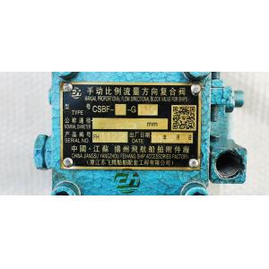
Marine manual proportional flow directional composite valve csbf-g25
Let's first familiarize ourselves with the working principle of csbf manual proportional flow composite valve
Principle of pressure compensation mechanism of marine manual proportional flow composite valve csbf-G25:
The oil in the motor pipeline flows from the oil inlet (Port P) of the manual proportional valve to the load (port a or port B) through the throttle port of the main valve element. At the same time, the lower surface of the diverter valve element also receives a force to push the valve element upward. The magnitude of this force is P1A (a is the cross-sectional area of the valve element). The pressure P1 decreases to P2 due to passing through the throttle port. P2 acts on the upper surface of the valve element to push the valve element downward, In addition, the action of the spring causes the valve core to receive a downward pushing force, so the downward pushing force is P2a + F (F is the spring force). If P2a + F > P1A is established, the valve core will be pushed downward, so that the throttle surface of the diverter valve is in a closed state, and the inflow flow is all led to the load through the throttle port of the main valve core. When the flow into port P increases, P2a + F < P1A, at this time, the valve element moves upward and the throttle surface opens, so that a large amount of flow flows out from port O and the flow through the throttle port decreases. Until f / a = P1 - P2, the valve element is in a stable state. If the load pressure rises, when f / a > P1 - P2, the valve element will be pushed downward to reduce the opening of the throttle surface, and P1 will also rise. Until f / a = P1 - P2, the valve element will be in a stable state again. If the load pressure decreases, then f / a < P1 - P2, at this time, the valve element will be pushed to the top, and the opening of the throttle surface will be increased, and P1 will drop accordingly until f / a = P1 - P2, and the valve element will be in a stable state again. Therefore, no matter how the inlet and outlet oil pressure changes, the pressure difference P1 - P2 remains constant, that is, it is constant, and the flow rate when passing through the throttle is also constant. Therefore, the flow rate is determined by its flow area and has no relationship with the change of load pressure.
Direction switching and throttling principle of main valve core of csbf-G25 manual proportional flow directional composite valve (taking M-type as an example):
When the handle is in the middle position, all oil ports (ports a and b) are closed. The oil discharged from the oil pump returns from port p to port o, and the oil motor stops.
The handle is on the right side, and the main valve element moves upward. The oil flowing in from port P flows to port a through the throttle port, and then flows out from port a to drive the oil motor to rotate. The return oil of the oil motor returns from port B to port O. at this time, the main valve element is at different positions by pulling the handle to adjust the opening of the throttle port to achieve the speed regulation of the oil motor. On the contrary, the handle is on the left side and the oil flow is from P-B to a-o. the results are completely similar, but the oil motor turns in the opposite direction.
Overflow principle of manual proportional flow compound valve csbf-G25 of windlass (safety valve part):
Similar to the principle of general overflow valve, when the load pressure of the oil motor is low, the cone valve is closed due to the spring force, and the oil motor operates normally. When the load pressure rises and exceeds the spring force on the poppet valve, the poppet valve opens and the high-pressure oil flows from port p to port o to protect the oil motor.
Use and maintenance of csbf-G25 manual proportional flow composite valve
1. When this manual proportional valve works, it is recommended to use industrial lubricating oils 46 and 68 (see gb3140-82) for the oil. The oil should be kept clean and the oil temperature should be recommended (20 ℃ - 60 ℃).
2. When installing the manual proportional flow composite valve, the installation position shall be convenient for operation and maintenance, and the installation can be in any direction.
3. The manual proportional composite valve shall be fixed on the processed base surface with screws. It is not allowed to support the valve with pipes.
4. During installation, check whether the inside of the valve is clean, and ensure that all connections are well sealed to prevent air from penetrating into the pipeline.
5. If there is leakage at the joint, check whether the installation screws, pipe threads are tightened, O-ring is missing, and the spring is damaged.
6. Remove the drain plug, install the leakage oil pipe joint, and introduce the leakage oil into the oil tank, otherwise the ball shaft at the handle will be broken (the schematic diagram of operation is as follows).
7. When the csbf-g25 manual proportional flow composite valve is operated, the operating direction and angle of the handle change, which can control the direction and flow of oil flow.
8. The two screws on the handle limit (as shown in the figure below) limit the maximum flow of the valve to reach the maximum speed of the machine.
When the manual proportional valve of our windlass is used for several years, the valve will undergo different degrees of corrosion, which will cause its function to decline. At this time, we can simply analyze the fault and repair it:
When none of the above conditions can be solved, we need to replace the whole proportional valve, which will cause us a problem. Because the nameplate on the proportional valve has been corroded for a long time, it is difficult to determine the accurate model. At this time, we can accurately judge according to the following information: